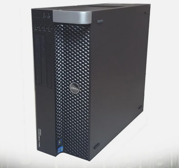
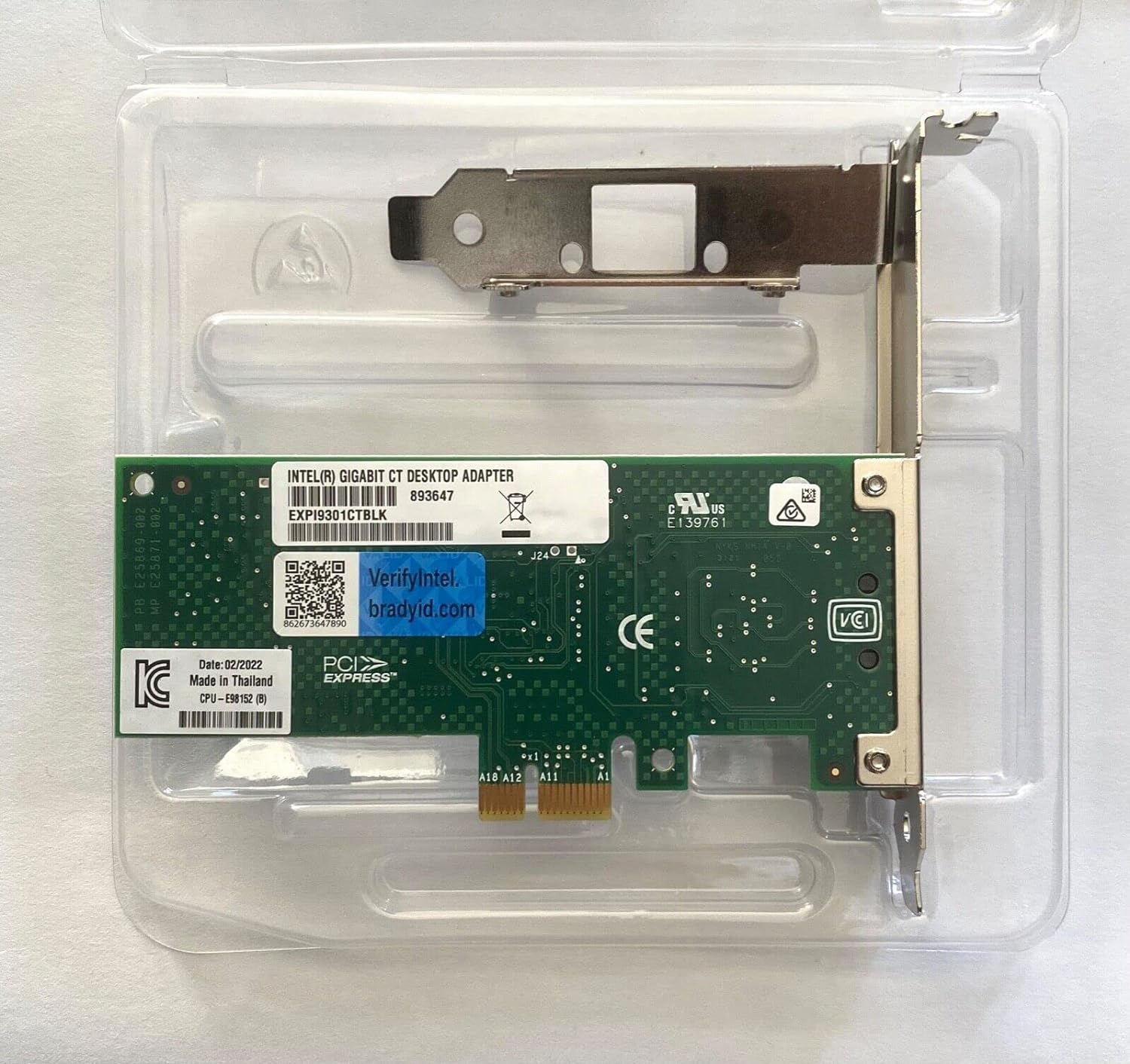
A homelab serves as a dedicated space for individuals to hone their IT and/or information security skills. When I first decided I wanted to pursue a career in IT, I quickly realized that reading theory, watching video demonstrations, and completing Udemy courses would not be enough for me to truly learn. I needed a way to practice what I was learning in a “hands-on” type of environment. Therefore, I made the decision to design and build a homelab that allowed me to experiment with anything from networking, virtualization, Active Directory, web servers, and Information Security tools and techniques.
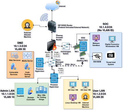
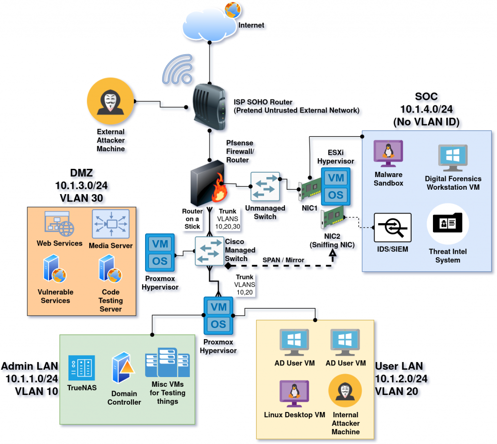
This blog post will cover how I designed the network portion of my home lab. I won’t be going into detail about any specific technologies that are not related to networking. The diagram below illustrates in detail the network topology of my homelab, serving as a reference for the rest of this blog post.
Hardware
Topology and Segmentation
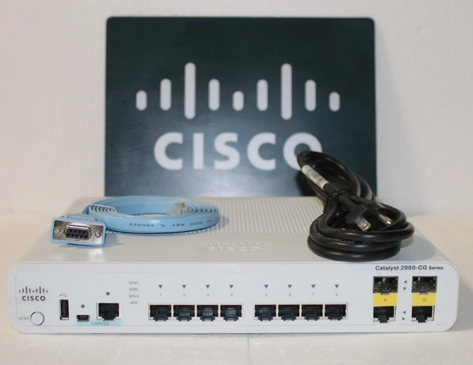
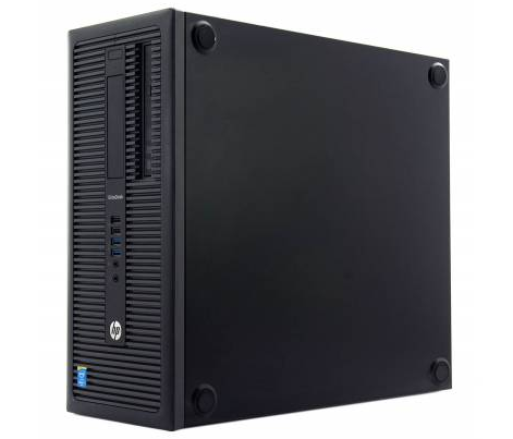
When I first started building my homelab, all I had for equipment was a used Cisco switch, my personal gaming PC, and a couple of old HP desktops I got for a bargain. With this equipment I designed a simple “flat network” with only one subnet. This means everything in my homelab was hosted within the same “LAN”. Although it was a good start, I wanted my homelab to feel a little bit more like a real corporate network. Therefore, I thought the next step was to plan out how to segment my network into distinct administrative subnets.
After a lot of googling in order to figure out what the average “corporate topology” might look like, I ended up settling on four subnets to divide my network:
- The “Admin LAN” at – 10.1.1.0/24
- This subnet contains the “internal services” of the network, such as a Domain Controller for Active Directory and my TrueNAS instance, where I store my movies, shows, and audiobooks.
- The interfaces of my network devices (router and switch) are also assigned to this subnet.
- My personal workstation also sits on this subnet, so that I can access everything an “admin” should access.
- Proxmox hypervisor runs VMs for both “Admin LAN” and “User LAN” by utilizing a trunk port, but the hypervisor itself is managed on Admin.
- The “User LAN” at – 10.1.2.0/24
- Practicing with Active Directory means that I also need a few fake “user workstations”. These are connected on this subnet.
- The “DMZ” at – 10.1.3.0/24
- Also stands for “Demilitarized Zone”.
- Real networks host services that have to interact with the public internet, which is an “untrusted” network. These services are usually put into what’s called a DMZ.
- A DMZ is just a network segment that sits between an organization’s “trusted” network and an external “untrusted” network. It is also configured with stricter firewall rules between it and the internal network segments so that those segments remain protected and isolated from a compromise.
- In my homelab, this DMZ isn’t actually interacting with the real internet. Rather it faces a “pretend” untrusted network that is actually just be the SOHO wireless router that my ISP provides. (This can be better understood from the network diagram above).
- This subnet is currently hosting my media servers (Jellyfin and Audiobookshelf). I also use it to spin up “vulnerable” web services to practice my penetration testing skills or simulate an “External Penetration Testing” assessment.
- VMs are running on a Proxmox hypervisor.
- Also stands for “Demilitarized Zone”.
- The “SOC” at – 10.1.4.0/24
- “SOC” stands for Security Operations Center. In the real world, a SOC is a unit within a company or organization that handles all of the network’s cybersecurity needs. SOCs monitor the network and try to prevent, detect, and respond to security incidents.
- This subnet is where I practice my cybersecurity skills. I currently have set up several tools running inside of an ESXi 7.0 hypervisor such as a SIEM (Security Onion), a Malware Sandbox, a Forensics Workstations, and Threat Intelligence Server.
Configuring Routing Interfaces on Pfsense
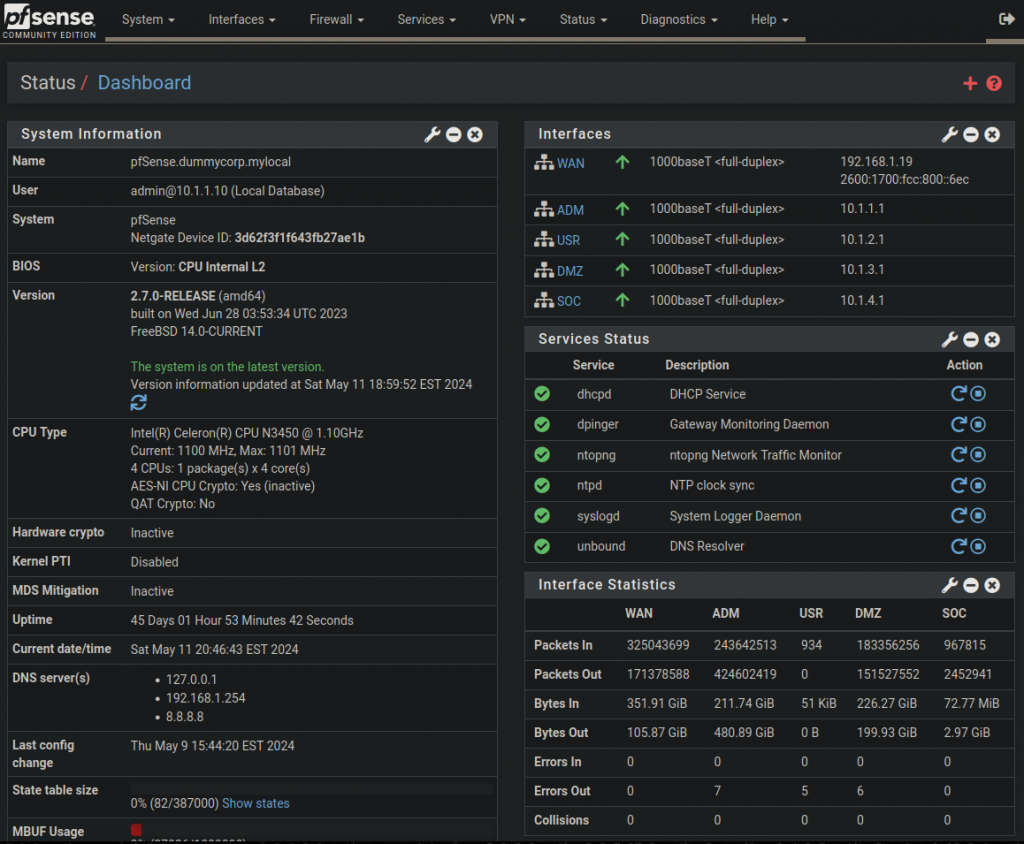
Pfsense is an all-in-one router/firewall operating system that can be installed for free on almost any x64 computer. Other than being just a router and firewall, it can perform countless other network roles such as DHCP, DNS, and can even work as a VPN service. Most importantly, Pfsense is free and open-source!
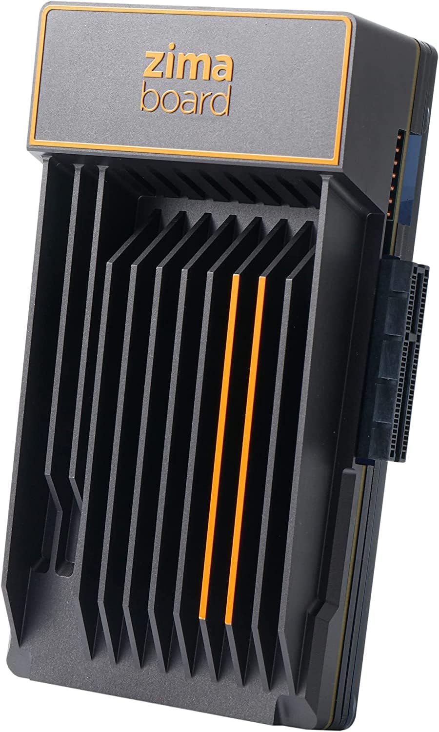
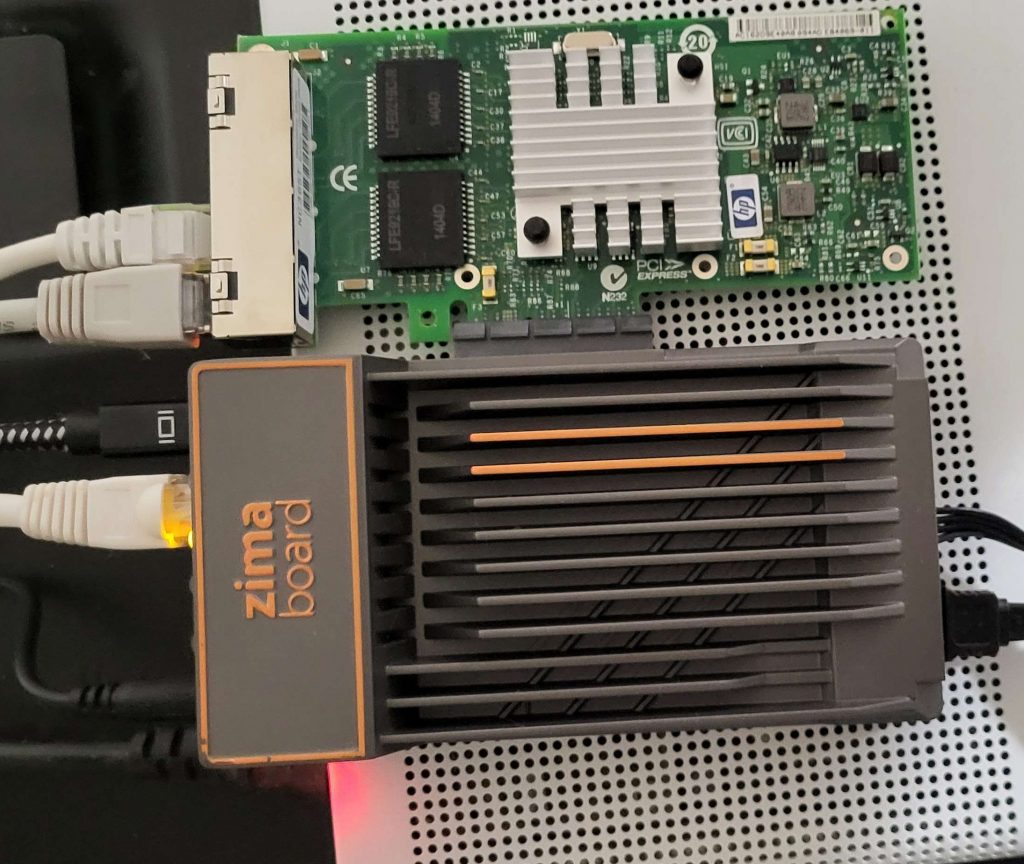
In my case, I’ve installed Pfsense on a neat piece of hardware called a Zimaboard. Similar to something like a Raspberri Pi, a Zimaboard is a low-powered, single board computer with lots of “expandibility” options built in. Unlike a Raspberri Pi, Zimaboards run on a x64 CPU rather than ARM. This is a good thing because the open-source version of Pfsense only works on x64 processors.
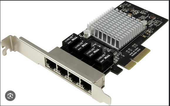
One of the coolest expandibility features of the Zimaboard is the PCIe slot. I’ve used this to attach 4 port network card to it. Now I’m able to utilize six interfaces instead of just the two already built in.
The first time I installed Pfsense was a bit of a task. I had to first burn the ISO onto a USB drive, install the operating system onto the Zimaboard, go through the configuration wizard, set up the DNS resolver, set up one interface to connect to my SOHO ISP router, and then assign the interfaces to the subnets that I came up with earlier. In the end, I ended up with a pretty cool and robust routing/firewall solution.
Configuring VLANS on a Cisco Switch
Of course, layer 3 routing cannot work without layer 2 switching. A router’s job is to de-encapsulate Ethernet frames, and then forward packets from subnet/LAN (local area network) to the next correct subnet based on the destination IP address and its routing table. Once a packet is re-encapsulated into an Ethernet frame again, the router’s job is finished, and a switch takes over. So, I needed a switching mechanism for each subnet I’ve created. The only problem was that I had four subnets but only two switches. That’s where VLANs come in handy.
VLANs, or Virtual Local Area Networks, are a way of segmenting LANs into smaller “broadcast domains”.
- If you’re unfamiliar with what a broadcast domain is, it’s basically the extent of a network where an endpoint could receive a broadcast message.
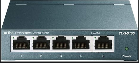
Using my managed switch, I created 3 VLANs (10, 20, and 30) for my ‘Admin’, ‘User’, and ‘DMZ’ subnets, but not for the SOC subnet. Instead, I connected to SOC to my unmanaged TP-Link switch which then connects to Pfsense. That way, there is more of a physical separation for the SOC.
To configure a switch to do VLANs:
- First you have to assign the switches physical ports to a VLAN.
- Then you have to configure at least one trunk port connecting to a router so that the VLANs can be routed to each other without wasting port interfaces. (Otherwise, I would have needed three different interfaces connecting to my Pfsense router).
Here are the commands for assigning a VLAN on a port:
- Enter enable mode then global configuration mode:
- enable
- configure terminal
- Enter interface configuration mode for the interface/s you want to configure:
- interface {interface name or range}
- Assign as ‘access mode’:
- switchport mode access
- Assign the VLAN ID:
- switchport access vlan {VLAN ID}
- Repeat for all interfaces that need editing
- Exit interface configuration mode and verify configuration.
- show vlan brief

Next, I configured two switch ports to be trunk ports. One was needed to connect to Pfsense. The other was needed to connect to one of my hypervisors because it hosted two VLANS, so it needed to be “VLAN aware”.
Cisco commands to configure a trunk port:
- Enter enable mode then global configuration mode:
- enable
- configure terminal
- Enter interface configuration mode for the interface/s you want to configure:
- interface {interface name}
- Set it to trunking mode:
- switchport mode trunk
- On some switches, you may have to choose a trunking protocol:
- switchport trunk encapsulation {dot1q or isl}
- Configure the list of allowed VLANs
- switchport trunk allowed vlan {list of vlans}
- Exit interface configuration mode and verify configuration.
- show interfaces trunk
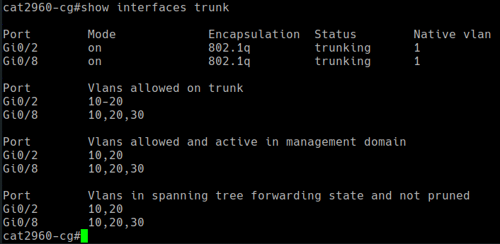
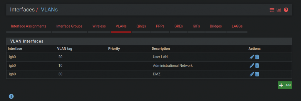
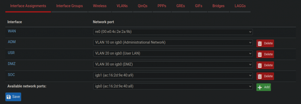
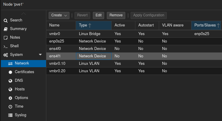
Trunk ports need to be configured on both ends, or two devices for each trunk. In my case, I configured trunking from the Cisco switch to Pfsense, and also from the Cisco switch to one of the Proxmox hypervisors. Making non-switch devices “VLAN aware” is done using a mechanism called “router on a stick”. This basically takes an interface on a routing device and divides it logically into “sub-interfaces”. For example, igb0 becomes “igb0.10” for VLAN 10, “igb0.20” for VLAN 20, and “igb0.30” for vlan 30. The screenshots below show those configurations:
Configuring Firewall Rules on Pfsense
At the most basic level, network firewalls are devices that filter traffic at the transport layer. There are two types of firewalls: stateless and stateful. Stateless firewalls examine traffic without considering the context or history of the network connection. Stateful firewalls keep track of active connections and consider and can allow or deny traffic based on packet history. They make an allow or deny decision based on context, rather than strictly following rules. Pfsense is a stateful firewall at the very least.
On Pfsense, and many other firewall software, rules work by “first match” bases and explicit deny. This means that when a connection is initiated, the firewall checks every rule sequentially, from top to bottom, to see if the connection matches any of the rules. The first rule that matches gets applied to the connection and either an allow, deny, or filter action is taken. If none of the rules match, the connection gets denied by default (explicit deny).
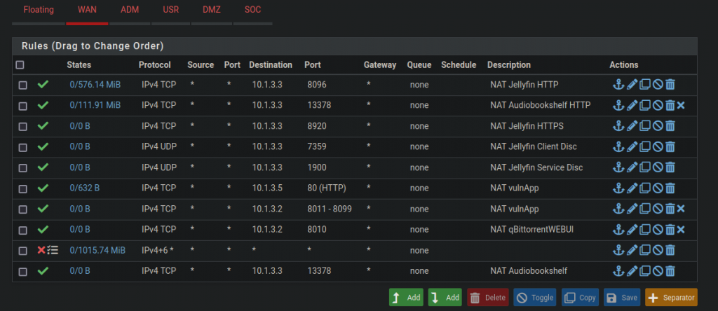
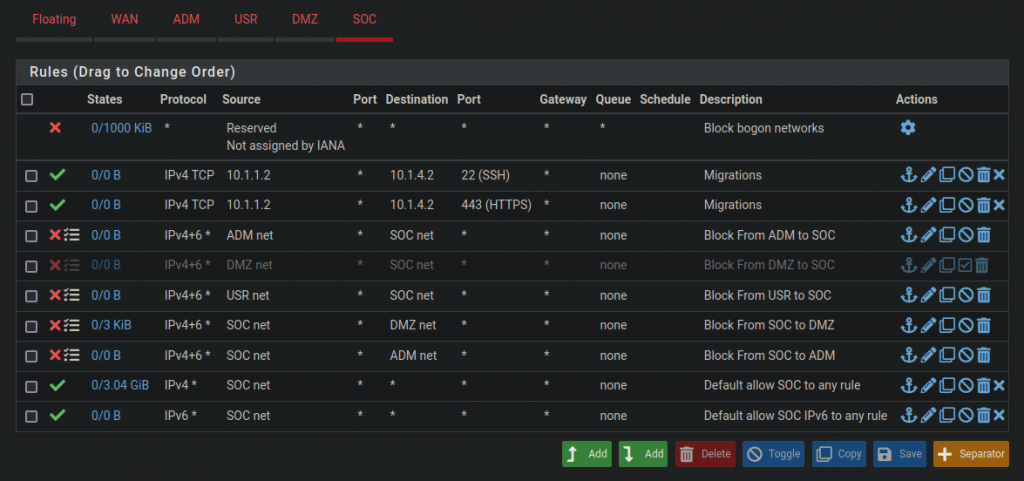
Rules are organized on Pfsense by giving each interface its own set of rules. The screenshots below show how I have my rules set up. The WAN rules allow a lot of port forwarding, while the SOC rules have stricter security.
SPAN Port
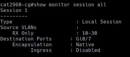
SPAN ports, also called ‘port mirrors’, allow the mirroring of traffic from a switch to another device using a designated port on the switch. In my homelab, I configured one of my switch’s ports to mirror all ingress traffic on VLANs 10, 20, and 30 via a secondary network card on my ESXi hypervisor in the “SOC” subnet. From there, it gets forwarded to a SIEM/IDS virtual machine where it gets analyzed. Mirroring traffic is an essential part of every Security Operations Center.
Future Use Cases
Well, that’s the gist of my homelab topography for now. Over the course of a year and a half, I’ve been able to set up a decent media server that’s able to transcode movies and TV shows, while also storing my media on a network-attached storage (NAS). I have also started to learn a lot about Active Directory services and file sharing technologies like SMB. In the future, I hope to keep building my SOC segment since information security is a subject that really interests me.
That’s it for now, thanks for reading!
